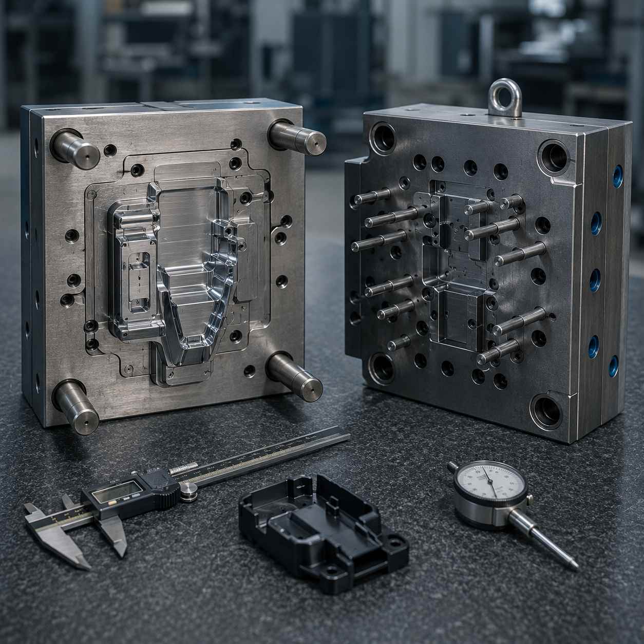
A new mold arrives at the plant, goes onto the injection molding machine, produces a few good-looking parts — and acceptance often ends right there. A month into production it turns out that one cavity consistently produces short shots, part of the cooling circuits is blocked, and an acceptable part only comes out within a narrow band of settings. Mold quality assessment is not a look at one showpiece part but a formalized procedure: checking documentation, mechanics, mold systems, and process behavior.
Below is a practical tooling acceptance protocol: what to look at with the mold disassembled, how to check clamping, cooling, venting, and ejection, what to evaluate during trial shots, and the criteria for signing off. Promservice designs and builds molds, runs trial shots on its own fleet of injection molding machines, and takes on tooling from other manufacturers for servicing.
Why acceptance is the last cheap point for corrections
Until the mold goes into production, any rework is planned toolroom work. Once production starts, the same operation costs an entirely different kind of money, so acceptance deserves to be run as a separate project stage with a scope of work, criteria, and documents.
- Production stoppage. The mold has to come off the machine, be disassembled, sent to the toolroom, and returned; the injection molding machine sits idle meanwhile.
- Scrap in the batch. Parts with a hidden defect are already molded, and they are often found at the customer's assembly line.
- Schedule slip and a weaker position. Every unplanned rework eats into time reserves that serial supply simply doesn't have, and once an acceptance report is signed "with no remarks," claims against the toolmaker are much harder to discuss.
The documentation package a mold must come with
A mold without documents is a black box: servicing and repairing it becomes guesswork. By the time of acceptance the customer should receive:
- 3D and 2D mold assemblies with sections and identification of the main units;
- a bill of materials for purchased components — hot runner, standard components, ejector pins, seals — with manufacturers and part numbers (Bohler, DME, Mold-Masters, Incoe, Pro Plastica, and others); this is exactly what you order a spare part from a year later, without taking the mold apart to investigate;
- a mold data sheet: number of cavities, weight, dimensions, required clamping force, ejection stroke, cavity and part marking scheme;
- steel grades and hardness of the molding inserts, cores, and plates;
- cooling circuit and hot runner wiring diagrams — with circuit numbering, connection sequence, heating zones, thermocouples, and connector layout;
- disassembly and maintenance instructions with service intervals and a list of replaceable inserts and spare parts to stock.
Visual and geometric inspection in the disassembled state
Accepting a mold only in the assembled state is a mistake: most defects are visible only when the mold halves are separated.
- Molding surfaces. Polish or texture must match the agreed class (SPI, VDI) equally across all cavities, not just in the showpiece one.
- Machining marks. Waviness from milling, unblended steps at toolpath transitions, and coarse relief left by sinker EDM where polishing was specified will all transfer to the part.
- Edges, undercuts, dings. Sharp edges near the parting line crush quickly, unintended undercuts block ejection, and corrosion marks or burrs on insert fits are unacceptable.
- Parting line and marking. Cleanliness, no galling or peening, uniform support surfaces; cavity numbers and part identification must be on the tooling itself, not only on the drawing.
Clamping and closing accuracy
The gap at the parting line is the main source of flash, and it has to be checked before the first shot.
- Parting line contact. A blue-check shows whether the surface makes contact around the entire cavity perimeter, not just in the center.
- Plate flatness and parallelism. Misalignment produces an uneven gap that also grows in production as the mold heats up.
- Guide pins and bushings. Travel must be smooth, without play; signs of binding indicate misalignment or an inaccurate fit.
- Taper locks and centering elements. They absorb the side load from injection pressure; without them deep inserts spread apart and the mold halves shift — visible as uneven wall thickness and a step on the parting line.
Runner and hot runner system
At acceptance what matters is not the choice between a hot runner and a cold runner, but whether the system already built into the mold actually works.
- Locating ring and sprue bushing. The bore diameter and spherical radius must match the nozzle of the specific injection molding machine, otherwise you get drooling and sprue breakage.
- Runner geometry and balance. Runners are polished in the direction of flow; for multi-cavity molds, balanced feed runners are the basis of uniform cavity filling.
- Heaters, thermocouples, and zone operation. Before the mold is installed, heater resistance and thermocouple continuity are measured — this reveals breaks and errors in connector layout; on the machine every zone must reach its setpoint and hold it, because a cold zone means a short shot in its cavity.
- Leak tightness and completeness. Melt leakage into the plate is a defect after which the mold is fully disassembled; cables and connectors must be labeled per the diagram.
Cooling system: pressure testing, flow, thermal survey
Just how much cooling drives cycle time and warpage we covered in detail; at acceptance it is enough to confirm the system is leak-tight, unobstructed, and delivers a predictable temperature pattern.
- Leak-tightness pressure test. A leak through seals, plugs, or insert joints will show up in production as moisture marks on the part and corrosion of the steel.
- Flow through every circuit. Each circuit is flushed: blocked or dead-end channels occur even in a new mold — from chips or a process plug that was never removed.
- Connection diagram and labeling. Inlets and outlets must be labeled, the diagram must match reality, and fittings and seals must suit the specific machine.
- Channel layout and temperature uniformity. Assess the distance to the molding surface and coverage of thick walls and deep cores; once at operating conditions, a thermal survey of both mold halves reveals hot spots the layout never anticipated.
Venting in critical areas
Insufficient venting shows up as burn marks, short shots, and weak weld lines and almost always requires steel rework, so it is checked before production. Look at the depth of the vent channels on the parting line — matched to the specific polymer, not "universal" — and at gas relief in the last-to-fill areas where air is pushed at the end of injection.
Venting is checked separately at weld lines and blind pockets, along with gas relief through ejector pins, inserts, and cores where parting line vents don't work, and the cleanliness of the vents after assembly: a clogged vent is worse than no vent at all.
Ejection and moving units
The mechanics are checked first on dry cycles, then with a part.
- Uniform ejection. The part must come off without cocking, without stress whitening, push-through, or residual deformation.
- Plate stroke and return. Full stroke per the data sheet, reliable return to the home position, return springs or positive retraction.
- Condition of ejector pins, fits, and witness marks. Play produces flash around the pin, binding produces galling; the location and depth of the marks are agreed in advance — where they are acceptable and where the surface is cosmetic.
- Slides, angle pins, locks. Smooth travel, no sticking, condition of the working surfaces and lubrication; rack mechanisms for threads are checked for synchronization under load.
T0 and T1 trial shots: what to evaluate on the parts
The first shots yield more information than any tooling inspection. They must be run on the same material and the same grade that will go into production.
- Complete filling of all cavities — including at reduced settings, where imbalance shows up most clearly.
- Part weight spread between cavities — a simple and telling indicator of runner system balance.
- Dimensions and warpage — preliminary, against the drawing, after the samples have stabilized, not while hot.
- Defects — short shots, flash, burn marks, sink marks, weld lines, silver streaking, ejector pin marks.
- Behavior at demolding — sticking in the cavity or on the core, the need to help the part out by hand.
The process window is the main criterion of mold quality
A mold that yields an acceptable part at only one point in the parameter space is programmed scrap in production. The real sign of quality tooling is a wide process window: the part stays acceptable when settings vary within reasonable limits. That is why acceptance deliberately tests how the mold behaves under deviations in:
- melt temperature and mold temperature;
- injection speed and injection profile;
- holding pressure and holding time;
- cooling time and overall cycle time.
If a minor deviation immediately produces flash or a short shot, that is not a "process characteristic" but a signal to rework the mold: clamping, venting, runner balance, or cooling.
Dimensional inspection, first article report, and stability test
Acceptance ends with measurements, not impressions. The minimum scope of inspection:
- measurement of critical dimensions per the drawing with actual values recorded, and CMM measurement for complex geometry and hole positions;
- inspection of all cavities, not one reference cavity;
- stabilization of samples before measurement — polymers keep shrinking after demolding;
- a sample from several cycles, to assess not only conformance but also dimensional spread.
Next comes the stability test: continuous running at the agreed settings for a series of cycles, with weight and dimensions checked on samples at the start, middle, and end of the run. What matters is a stable cycle time without manual intervention, no growth of flash as the mold heats up, and no sticking or ejection faults. The result is documented: agreed process settings, a reference sample, and acceptance criteria.
Mold life and serviceability before production starts
- Steel matched to volume and material. Grades and hardness of the molding features must match the expected output; glass-fiber or mineral-filled compounds wear steel far faster than unfilled ones.
- Replaceable inserts in wear zones. Parting line edges, gates, and thin cores are better made replaceable than integral with the plate.
- Availability of standard components and spares. Components from known manufacturers are replaced from a catalog, while unique shop-made elements have to be remade from scratch; the minimum to stock is critical ejector pins, seals, a hot runner heater and thermocouple, and replaceable inserts.
- Servicing without full disassembly. Cleaning vents and replacing an ejector pin or a seal must be possible right at the molding shop.
Consolidated acceptance checklist
A compact list to sign the acceptance report against:
- Documentation, bill of materials, and mold data sheet handed over.
- Disassembled inspection performed; condition of molding features and marking match the drawing.
- Parting line contact, plate parallelism, guides, and locks checked.
- Runner system and hot runner functional; heating zones and thermocouples working.
- Cooling circuits pressure-tested and unobstructed; venting present in critical areas and not clogged.
- Ejection uniform; slides and moving units run smoothly.
- All cavities fill, weight spread within agreed limits, process window verified.
- Dimensional inspection of all cavities completed, stability test passed, settings and reference sample recorded.
- List of replaceable inserts and spare parts to stock agreed.
Common acceptance mistakes
- Accepting a mold on one "beautiful" part. It shows neither cavity balance, nor stability, nor the width of the window, and in a multi-cavity mold the problem is usually one specific cavity rather than the mold as a whole.
- Skipping the cooling pressure test. An internal leak is then found in production — together with corrosion of the molding features.
- Ignoring the process window. A mold running "on the edge" delivers steady scrap the moment the resin lot changes.
- Not demanding documentation. Without a bill of materials, any repair starts by taking the mold apart.
- Accepting on a substitute material. A different polymer grade means different shrinkage, viscosity, and filling behavior.
- Not recording a reference sample and criteria. Without an agreed sample, a quality dispute in production has nothing to stand on.
How Promservice helps with tooling acceptance and launch
We run full-cycle mold projects within a quality management system per ISO 9001:2015 and can step in precisely at the tooling assessment and launch stage:
- we design and build molds with a full documentation package, bill of materials, and cavity marking;
- we run trial shots on our own fleet of injection molding machines from 50 to 650 tons (Arburg, Bole, Engel, Haitian) using the production-grade material;
- we check clamping, the runner and hot runner system, and pressure-test and flush the cooling circuits;
- we dial in the process settings and evaluate the width of the process window, not just a single operating point;
- we perform dimensional inspection of samples from all cavities and issue the measurement results;
- we rework tooling in our own shop — venting, cooling, gates, replaceable inserts, correction of molding features on CNC and EDM;
- we take the mold on for ongoing maintenance, repair, upgrades, and storage at our facility.
Need a mold quality assessment before production?
If you are taking delivery of new tooling or transferring someone else's mold to a new plant, mold quality assessment before production starts is the cheapest way to avoid stoppages and scrap. Send the 3D model, part drawing, a sample part, and the mold documentation — we'll review the design, run trial shots and dimensional inspection, and give you a list of the rework required.
Promservice designs, manufactures, and services molds, and provides serial plastic injection molding on its own fleet of injection molding machines.