Against complex 3D milling and EDM, turned mold components are sometimes treated as “simple cylinders.” In reality, these parts often define mold life, repeatability, and maintainability.
Guide systems control how accurately the plates close. The sprue bushing controls nozzle sealing and stable melt feed. Core pins and forming cores control part geometry and clean release. A mistake of a few hundredths of a millimeter can lead not to “cosmetic issues,” but to galling, misalignment, flash, nozzle leakage, and accelerated wear.
This article is a practical guide to:
- what is typically turned for injection molds;
- which tolerances are truly critical;
- where coaxiality and surface finish matter most;
- why “saving on accuracy” usually returns as repair work.
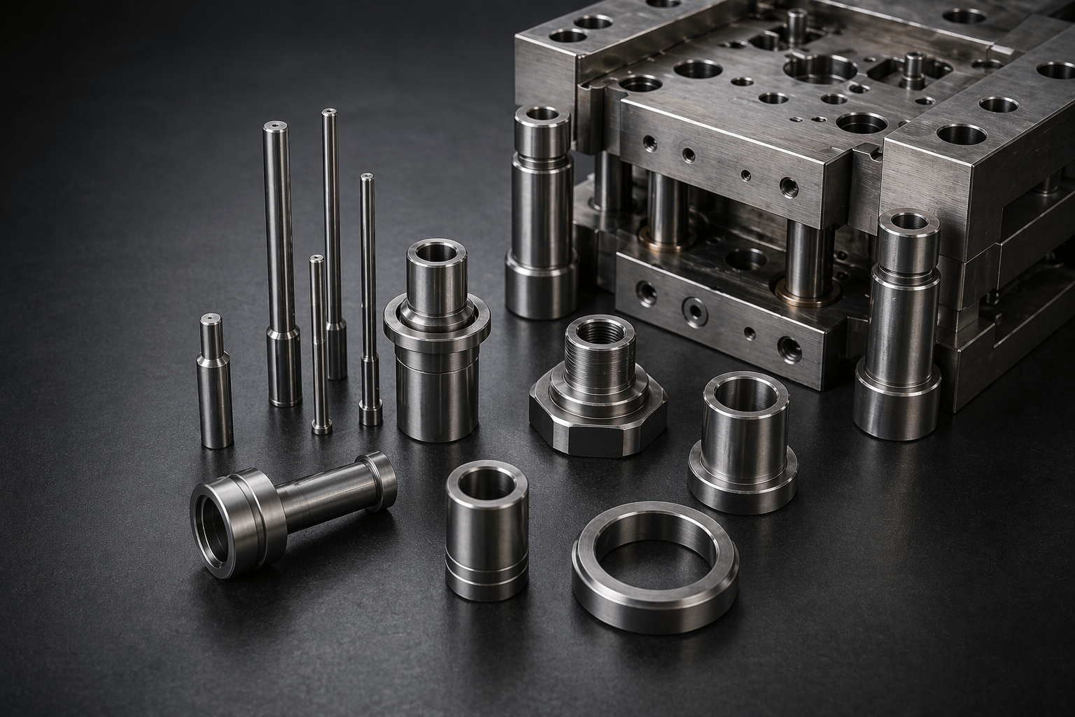
What is typically turned for molds
In tooling, “turned parts” are not limited to shafts and sleeves. Most often, CNC lathes produce:
- guide pins/leader pins and guide bushings (plate guiding systems);
- sprue bushings and other axially symmetric runner elements;
- core pins, forming cores, stepped pins (including multi‑diameter parts);
- ejector sleeves and guiding components for the ejection system;
- support pillars and spacers;
- locating rings and centering elements;
- threaded connectors, caps, cooling fittings (depending on design).
These parts almost always work as a pair with other components. Therefore, the goal is not “tight tolerances everywhere,” but the right fit + correct mutual position.
The 5 tolerance groups that actually define mold life
1) Fits and clearances: sliding, press‑fit, and centering
In a mold you usually have three fit scenarios:
- sliding fits (guiding, ejectors) — predictable clearance without seizure and without play;
- press fits (bushings pressed into plates) — no rotation, no movement in the seat;
- centering fits (locating/centering elements) — repeatable assembly and alignment.
Not only the nominal size matters, but also size stability along the length and from batch to batch.
Practice note: for guide systems, clearances are typically in the hundredths of a millimeter range. The exact value depends on diameter, temperature, lubrication, and the mold class.
2) Coaxiality, runout, cylindricity: when a “cylinder” is not just a cylinder
Even with the correct diameter, a part can destroy repeatability if:
- steps are not coaxial (coaxiality error);
- the surface is oval (roundness is off);
- the part is slightly bent (poor straightness);
- seating surfaces have runout relative to the functional axis.
These parameters are especially important for long guide pins, core pins, and sprue bushings.
3) Surface finish (Ra): from “how it slides” to “how it releases”
There are two scenarios where surface finish is decisive:
- sliding pairs (guides, ejectors) — roughness promotes galling and fast wear;
- forming/release (core pins, forming cores) — scratches on parts, sticking, unstable release.
Surface finish is usually specified as Ra; the required level depends on the task. The higher the expectations for release and lifetime, the more important proper finishing/polishing becomes.
4) Lead‑ins, chamfers, and transitions: small details that prevent galling
Chamfers, radii, and relief grooves are not “cosmetics.” They provide:
- safe assembly without burr‑damage;
- correct lead‑in and self‑centering during installation;
- lower stress concentration on thin pins;
- better lubrication behavior where grooves are designed.
Ignoring these features often results in seizure and premature damage during early cycles.
5) Condition after heat treatment: hardness without distortion
Many turned components operate under friction and require wear resistance. After hardening / nitriding / case hardening you can easily get:
- distortion (size and geometry drift);
- increased ovality;
- residual stress → cracking risk on thin parts.
That is why the process route is critical: machining → hardening → grinding/lapping → inspection.
Part‑by‑part: where tolerances matter most
Guide pins and guide bushings
Function: accurate closing and repeatable plate alignment in every cycle.
Critical parameters:
- clearance in the pin‑bushing pair (too tight → seizure, too loose → play and misalignment);
- straightness and cylindricity (a long pin with a slight bend will gall quickly);
- surface finish of working areas (smooth sliding = long life);
- press fit of the bushing in the plate (no rotation, no movement);
- proper chamfers and protective radii.
Typical problems when accuracy is compromised:
- guide wear and increasing play → flash at the parting line;
- seizure → damaged guides and machine downtime;
- unstable lubrication and overheating.
Sprue bushing
Function: sealing with the molding machine nozzle and stable melt feeding into the runner.
Critical parameters:
- coaxiality of the sprue channel relative to the seating geometry;
- surface finish and cone/seat accuracy (waviness or marks can cause leakage and unstable injection);
- runout of seating surfaces (uneven nozzle contact = unreliable seal);
- correct entrance/transition geometry (stable sprue break and consistent sprue mark).
What “saving” leads to:
- material leakage and contamination;
- overheating traces and part quality issues;
- fast wear in the nozzle contact zone.
Core pins and forming cores
Function: forming holes, inner features, and internal contours.
Critical parameters:
- coaxiality of steps (especially on multi‑diameter pins);
- roundness and cylindricity (for uniform contact and predictable release);
- surface finish in contact with plastic (release + appearance);
- transition radii (thin pins hate sharp stress risers);
- if the pin works inside a guide sleeve, clearance and sliding quality become critical too.
What “saving” leads to:
- plastic scuffing → visible defects on parts;
- higher ejection force → risk of pin breakage;
- faster wear and unstable dimensions due to misalignment.
Ejector pins, sleeves, and guiding elements of the ejection system
Function: repeatable, “soft” part ejection without tilt or marks.
Critical parameters:
- clearance in pin‑sleeve pairs (free movement without play);
- coaxiality and straightness (misalignment → jamming, galling, part marks);
- surface finish (reduces dry friction and seizure risk).
Locating rings and centering elements
Function: positioning the mold on the molding machine and repeatable installation.
Critical parameters:
- concentricity relative to mold datums;
- stable seating (especially for molds that are frequently removed/installed);
- flat, clean functional faces that actually “seat” in the machine interface.
If centering is unstable, the risk of nozzle‑to‑sprue misalignment increases and setup time grows.
Why accuracy here is “more expensive” than it looks
A turning error inside a mold is multiplied by:
- the number of cycles (hundreds of thousands);
- friction (wear accelerates non‑linearly);
- downtime cost (mold stopped = machine stopped = delivery at risk).
Typical “saving” scenarios:
- a little extra clearance → seems fine at first, then turns into play and flash after weeks/months;
- poor coaxiality on a stepped core pin → worse release, higher ejection load, breakage risk;
- rough sprue bushing seat → leakage, unstable injection, contamination around the nozzle.
In practice, repair and rework almost always cost more than doing it right from the start.
How stable geometry is achieved: a mold‑grade manufacturing route
For critical turned mold components, the most reliable route looks like this:
- Rough turning with allowance for hardening/finishing.
- If needed: stress relief (for larger parts).
- Heat treatment / surface hardening according to the wear scenario.
- Grinding / lapping of seating and working surfaces to restore size, roundness, and Ra.
- Inspection: dimensions, runout/coaxiality, surface finish, fit behavior in the pair.
This approach is especially important for guide systems and sprue bushings.
RFQ checklist: what to specify so the part fits without surprises
If you order turned tooling components, it is worth specifying upfront:
- the function of the part and the mating component it works with;
- the required fit type (sliding / press / centering) and, if applicable, fit designation;
- requirements for coaxiality/runout/straightness and what the datum is;
- surface finish (Ra) in working zones;
- material and condition (pre‑hardened, hardened, nitrided, etc.);
- cosmetic restrictions (for forming cores);
- operating conditions: temperature, lubrication, plastic type, production volume.
Better input data = faster, more reliable output.
Turned mold components for your project
Promservice provides metalworking and mold manufacturing as a full cycle: CNC turning and milling, EDM, grinding, polishing, heat treatment, and quality control.
If you need guide elements, sprue bushings, core pins, or other turned mold parts — send a drawing/3D model or a sample. We will help define what is critical, translate it into a clear specification, and manufacture components that work for lifetime, not for “early repair.”