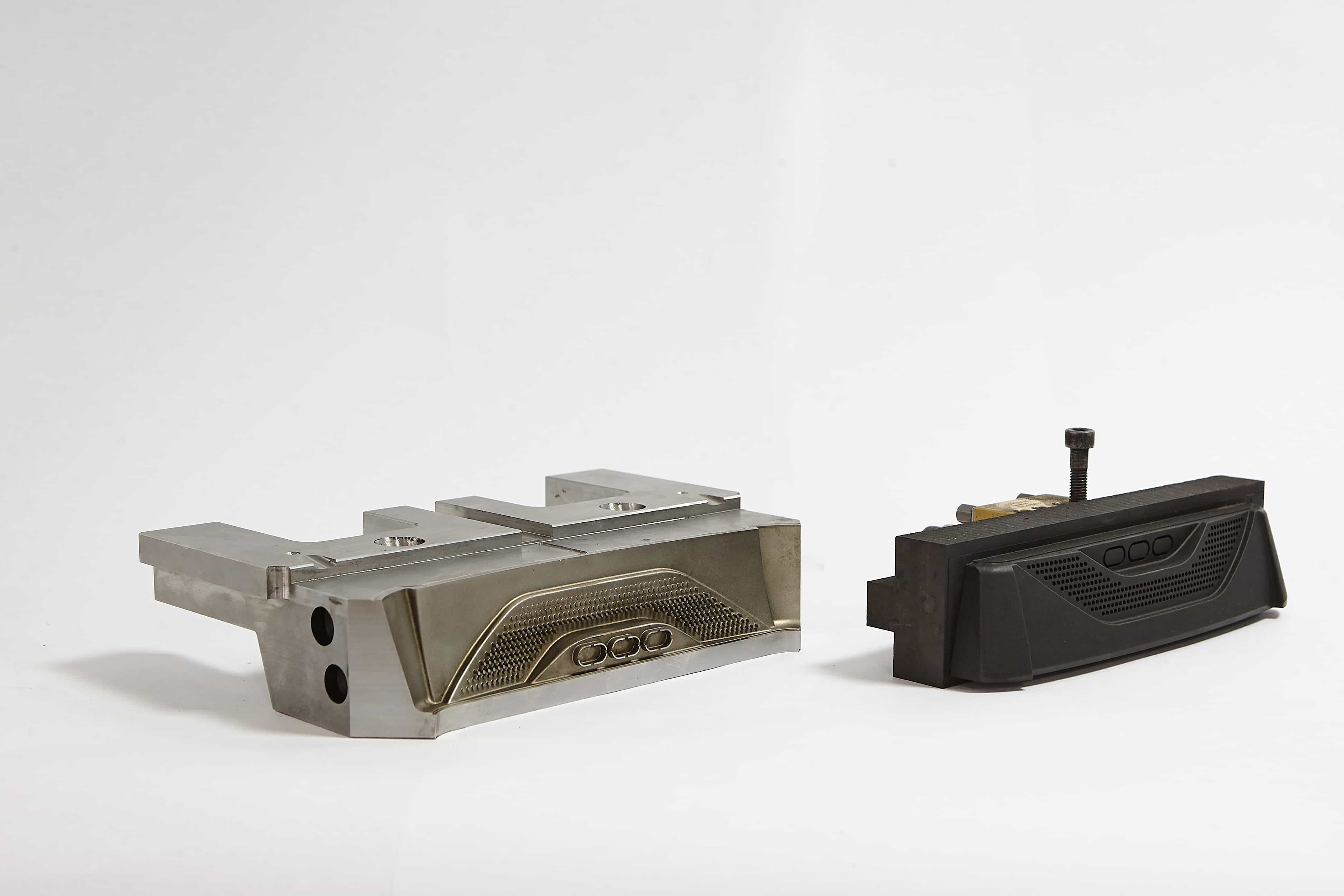
EDM (electrical discharge machining) is often the “last resort” when milling cannot reach deep ribs, sharp internal features, or hardened tool steels. But in mold making, EDM is also a smart way to protect critical geometry and reduce the risk of tool breakage in narrow areas.
The catch is that EDM quality depends heavily on the electrode. If the electrode is designed and machined incorrectly, you lose time twice: first on electrode rework, then on extra burns, manual polishing, or even part replacement.
This article is a practical guide on how to manufacture EDM electrodes (mostly for sinker / die-sinking EDM) so that:
- cavity dimensions “match” the model and tolerances;
- you do not fight unexpected overcut, taper, or corner rounding;
- electrode wear is predictable and controlled;
- finishing/polishing is minimized.
Promservice supports mold manufacturing with CNC milling, EDM, grinding/finishing, and inspection — including electrode machining from graphite or copper.
Where EDM electrodes are used in injection mold manufacturing
Electrodes are most commonly applied where “normal” milling becomes inefficient or risky:
- deep and narrow ribs, thin slots, and hard-to-reach pockets;
- sharp internal corners (within realistic radii limits);
- hardened inserts, cores, and cavities after heat treatment;
- texturing areas where surface quality is critical;
- small details that would require extremely long, fragile end mills.
A good rule: milling removes the bulk, EDM protects the details. The more clearly you split “milling zones” and “EDM zones” at the design stage, the fewer surprises you get later.
Graphite vs copper: which electrode material to choose
Two materials dominate in mold work: graphite and copper (sometimes copper alloys). Each has a “best use” profile.
Graphite electrodes: when they are a strong choice
Graphite is popular because it is:
- fast to machine on CNC (high spindle speed, low cutting force);
- stable in many roughing and semi-finishing EDM operations;
- available in different grades for roughing vs fine detail;
- often a cost-effective option for larger electrodes.
Typical use cases:
- roughing electrodes for deep cavities;
- multiple electrodes for serial work;
- larger pockets where edge micro-detail is not the limiting factor.
What you must plan for:
- graphite dust control and proper extraction;
- fragile edges if the grade/tooling is wrong;
- electrode sealing/handling (depending on the workflow).
Copper electrodes: where copper wins
Copper is often chosen when you need:
- very fine details and stable small edges;
- better surface quality in finishing burns;
- higher rigidity for thin features (depending on geometry).
Typical use cases:
- finishing electrodes for visible surfaces;
- small, precise features where the electrode edge quality matters most;
- demanding surfaces where polishing time must be reduced.
What you must plan for:
- longer CNC machining time vs graphite;
- burr control (burrs “print” into the cavity);
- careful tool selection and coolant strategy.
Practical takeaway: it is very common to use graphite for roughing and copper for finishing when the project requires both productivity and surface quality.
Electrode strategy: why “one electrode” is rarely enough
A frequent cause of rework is trying to burn the entire cavity with a single electrode.
In real production, an efficient strategy often includes:
- Roughing electrode: removes the main volume quickly, with a larger gap/offset.
- Semi-finishing electrode (optional): stabilizes geometry and reduces the finishing load.
- Finishing electrode: achieves final size and surface quality, with controlled small offsets.
- Spare/duplicate electrodes: for deep burns or when wear must be tightly controlled.
This approach reduces the risk that the finishing electrode “dies” before it reaches the target size.
The key numbers: spark gap, overburn, and machining allowances
Electrode manufacturing is not “copy the cavity and cut it.” You must account for the EDM process itself.
Spark gap (EDM gap)
EDM removes material across a gap between electrode and workpiece. That means the cavity will become larger than the electrode.
So, to hit the final cavity size, you must define the correct offset (sometimes called overburn allowance). The correct gap depends on:
- the workpiece material and hardness;
- EDM generator settings (rough vs finish);
- flushing conditions and cavity depth;
- required surface quality.
Because these factors vary, the safest workflow is: define offsets together with the EDM technologist (or use validated shop standards), not “guess by habit.”
Machining allowances for EDM vs milling
A practical workflow in mold manufacturing is:
1) Mill the cavity leaving a controlled stock for EDM in problem areas.
2) Burn only the zones that truly need EDM.
3) Finish with a dedicated finishing electrode where needed.
This reduces EDM time and makes sizing more predictable.
Wear compensation: how to keep size from the first burn to the last
Electrode wear is normal — but uncontrolled wear causes taper, corner rounding, and size drift.
Typical wear “hot spots”:
- sharp edges and thin ribs;
- deep cavities with limited flushing;
- corners where the discharge concentrates.
Common ways to control wear:
- use a dedicated roughing electrode and save the finishing electrode for the final pass;
- split deep cavities into stages (multiple electrodes, or depth steps);
- plan duplicates for finishing electrodes (especially in serial production);
- use stable referencing and measure electrode length/geometry between burns;
- consider orbiting strategies (where applicable) to stabilize finishing.
If you ignore wear planning, you often end up “chasing the size” with extra burns and manual polishing.
CNC milling electrodes: best practices for graphite
Graphite electrodes mill fast, but they punish poor process control.
Practical tips:
- use proper dust extraction (graphite dust is abrasive and messy);
- keep tools sharp; select tools suitable for graphite (chip evacuation matters);
- avoid “edge tapping”: unstable tool engagement chips fragile corners;
- use finishing toolpaths that reduce scallops on functional faces;
- protect thin features with realistic minimum thickness and corner radii;
- plan for safe handling and storage (graphite edges damage easily).
CNC milling electrodes: best practices for copper
Copper electrodes usually fail because of burrs and unstable small tooling.
Practical tips:
- choose toolpaths that minimize burr formation on edges;
- include a deburring step where needed (burrs will be transferred to the cavity);
- keep tooling rigid (short stick-out) and use stable feeds to avoid chatter;
- monitor tool wear closely on small cutters;
- control surface finish on functional faces — copper can deliver very clean results, but only with correct finishing.
Referencing and inspection: making EDM setups repeatable
Even a perfect electrode does not help if it is set up inconsistently.
To keep EDM predictable:
- define clear datums on the electrode (and on the workpiece insert);
- use a stable holder system and keep holder interfaces clean;
- mark electrodes (set number, burn stage, orientation) to avoid mix-ups;
- measure critical faces and key dimensions after milling;
- for complex electrodes, consider CMM inspection or a measurement report.
Repeatability starts at the electrode holder, not at the EDM machine.
Typical mistakes that cause extra burns and rework
Here are the issues that most often lead to “the size doesn’t match”:
- No spark gap allowance (electrode copied 1:1 from cavity).
- Trying to do rough + finish with one electrode (wear ruins the finish stage).
- Wrong material choice (graphite grade too weak for fine edges, or copper where productivity matters more).
- No wear control plan for deep cavities (taper and size drift).
- Poor flushing consideration (unstable burning, overcut, surface defects).
- Burrs on copper electrodes (prints into the cavity, increases polishing).
- Fragile corners without radii (electrode chips during machining or handling).
- Unstable referencing (different zero each time → unpredictable mismatch).
- No “electrode set management” (mixing rough/finish electrodes or orientation).
- Skipping inspection before EDM (errors discovered only after burning).
Checklist for ordering EDM electrodes (or electrode machining)
To make the result predictable, provide:
- 3D model of the cavity/insert (STEP preferred) and drawing tolerances;
- which zones will be EDM vs milled (or allow us to propose the split);
- steel grade and hardness condition (pre-hardened / hardened);
- required surface quality (critical cosmetic zones vs functional zones);
- production volume (prototype vs serial), to define the electrode set strategy;
- any existing EDM standards in your shop (preferred offsets, finishing classes).
The more clearly the goal is defined, the fewer iterations the project needs.
Need EDM electrodes for your mold project?
Promservice manufactures mold components and provides CNC milling and EDM support — including electrode machining from graphite and copper with controlled datums and inspection.
Send your model/drawings and requirements, and we will propose an electrode strategy (rough/semi/finish), offsets, and a manufacturing route that reduces re-burns and manual polishing.