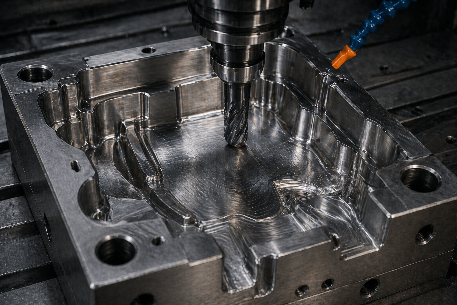
A mold cavity is where geometry, surface quality, and tool life “meet” in one place. This is also where extra hours of benching often appear: visible tool marks, steps on transitions, uneven remaining stock, or areas that need to be blended by hand.
A well-designed CNC strategy helps you achieve two important results at the same time:
- stable geometry (predictable dimensions and fits);
- less hand finishing / polishing (faster launch and lower mold cost).
At Promservice, mold manufacturing is built as a single process chain: design → machining (CNC milling, EDM) → grinding/fitting → polishing and inspection. That’s why we plan CAM operations upfront so the cavity surface is predictable and repeatable — not “fixed later.”
Below is a practical guide to machining mold cavities with a roughing → semi-finishing → finishing workflow, including HSM toolpaths, typical stock logic, tool selection for tool steels, and what to check for surface quality.
Why you can’t “just mill the cavity” in one go
Most cavities are not simple flat faces. They typically combine:
- deep pockets that require long tool reach;
- sloped 3D surfaces where the tool mark pattern matters;
- radii where side cutting amplifies vibration;
- critical shut-offs and parting features where fit is everything;
- surfaces that will be polished or textured (where defects will show on the part).
If you try to go from “remove metal” straight to “finishing,” you usually get variable tool load, uneven stock, chatter, and a surface that demands manual rework.
The 3-step workflow: the goal of each stage
1) Roughing Goal: remove volume fast while keeping the setup rigid and the tool load stable.
2) Semi-finishing Goal: create uniform remaining stock so finishing runs in consistent conditions.
3) Finishing Goal: hit geometry and surface requirements with minimal risk and minimal bench work.
Key idea: semi-finishing is not optional insurance — it often saves more time than it takes.
1) Roughing: HSM toolpaths that keep load consistent
For mold cavities, roughing works best with toolpaths that control engagement and keep cutting forces steady:
- adaptive clearing / dynamic milling;
- trochoidal milling;
- high-feed approaches where they make sense.
Tool steels don’t like sudden overload. Constant engagement reduces chatter, improves tool life, and makes the rest of the process more predictable.
Choosing the roughing strategy for your cavity
- Deep cavities: prioritize adaptive toolpaths with controlled engagement to prevent overload at depth.
- Wide pockets: more aggressive adaptive clearing can work, but keep chip thickness under control.
- Thin walls / flexible areas: keep support stock so the part doesn’t “move” and walls don’t start vibrating.
Roughing stock: how much to leave
There is no single correct number, but the logic is clear:
- too little stock → finishing hits heavy spots, you get steps/chatter and local overcuts;
- too much stock → semi-finishing and finishing turn into “another roughing,” increasing time and risk.
A common starting range (then refined for the real cavity, steel, and depth):
- leave roughly 0.3–0.8 mm on walls/surfaces for semi-finishing + finishing.
Roughing tool choice
For tool steels, roughing typically uses:
- carbide end mills with a corner radius (more durable edge, lower chipping risk);
- geometry that evacuates chips well;
- the shortest possible tool overhang (extra length = extra vibration).
When long reach is unavoidable, it’s often better to split the process: short tool for accessible areas + longer tool only where needed, instead of trying to do everything with one long end mill.
2) Semi-finishing: make the stock uniform and “prepare” finishing
Semi-finishing is what makes finishing stable. The goal is uniform remaining stock everywhere.
This step usually decides whether finishing will produce a clean, consistent surface — or whether it will “fight” variable loads and leave marks.
Typical semi-finishing operations
Rest machining Remove what roughing could not reach (fillets, narrow regions, transitions).
Stock equalization Create consistent stock for finishing — no low spots, no heavy areas.
Cleanup in fillets and intersections (pencil / cleanup) Eliminate ridges along surface intersections where leftovers are common.
Semi-finishing stock: what to leave for finishing
Finishing tends to be stable when a small but reliable stock is left after semi-finishing. Commonly:
- 0.10–0.30 mm on the surface (depending on tolerance, cavity size, and finishing strategy).
If EDM, texturing, or high-gloss polishing is planned, stock and routing must be coordinated so the whole process chain stays consistent.
A common mistake: skipping semi-finishing
Going straight from roughing to finishing often causes:
- uneven cusp height across the surface;
- chatter marks on transitions;
- local overcuts where roughing left a “step;”
- more benching and polishing.
3) Finishing: surface strategy and step-over control
Finishing is rarely “one toolpath.” Different areas of the cavity benefit from different strategies:
- steep walls often finish best with waterline (Z-level);
- shallow 3D surfaces often finish best with parallel, spiral, or morph;
- mixed surfaces often need constant scallop / morph to keep the tool mark quality consistent.
Selecting finishing toolpaths by surface slope
A practical rule:
- Mostly vertical → Z-level (even step pattern along height).
- Mostly horizontal → parallel/spiral (stable tool mark pattern).
- Mixed transitions → constant scallop or morph (consistent cusp height across slopes).
Step-over and scallop height: how to connect CAM settings to surface quality
For 3D finishing, the key parameter is cusp height. Smaller cusp height usually means less polishing time.
A quick practical relationship for a ball nose tool:
h ≈ s² / (8R)wherehis cusp height,sis step-over, andRis the tool radius.
Example: with R = 5 mm (Ø10 ball nose) and target h ≈ 0.005 mm, step-over is about 0.45 mm. It’s not a universal rule, but it helps translate “surface requirement” into CAM parameters.
Finishing tools: what actually makes the surface
Common options:
- ball nose end mills (general 3D finishing);
- toroidal / bull-nose cutters for walls and blended radii — often better durability and a “softer” tool mark;
- barrel cutters (barrel / conical barrel) where geometry and CAM allow, to increase finishing productivity without sacrificing surface quality.
Tool selection must match access and overhang. Sometimes a slightly smaller tool with a rigid setup gives a better surface than a larger tool on a long, unstable reach.
Tool steels: what matters for tooling and strategy
Molds often involve tool steels in different conditions:
- pre-hardened steels — easier to machine, but you still need stable geometry and a consistent tool mark pattern;
- hardened steels — require a stricter approach: short overhang, stable engagement, high-quality tooling, and the right toolpath.
What typically improves stability and surface quality:
- minimize tool overhang and use rigid holders;
- avoid sharp direction changes and sudden engagement spikes;
- control tool wear (a worn tool ruins finish faster than many expect);
- keep critical “A-surface” finishing away from the end of tool life.
Surface and geometry control: what to check during the process
To avoid “long benching,” control two groups of parameters.
1) Geometry and fits
- datums and parting/shut-off surfaces;
- insert seats and forming components;
- key 3D dimensions per the drawing/spec;
- positional repeatability (especially in multi-cavity molds).
2) Surface quality
- consistent tool mark pattern (no “different texture zones”);
- no chatter waves or vibration scratches;
- controlled roughness / finish for the required SPI/VDI (if specified);
- no local defects in cosmetic areas.
Catching issues after semi-finishing or finishing often saves more time than it takes — you fix the problem at the machine, not at the bench.
Typical issues: why finish quality drops and benching grows
In most cases, it’s not “bad machines,” but a combination of common mistakes:
- non-uniform stock (semi-finishing skipped or too light) → unstable finishing;
- step-over too large → high cusps and long polishing time;
- tool overhang too long → chatter and visible marks;
- wrong toolpath for the slope (e.g., parallel on steep walls) → steps and inconsistent pattern;
- poor tool sequence → finishing ends up removing heavy leftovers;
- worn tool used for finishing → finish collapses even with “good” CAM parameters;
- chip evacuation problems in deep cavities → re-cutting chips and surface defects.
If these are addressed early, finishing becomes predictable.
The Promservice approach: less hand work through a correct process route
In mold manufacturing, we aim to “build in” surface quality at the CAM stage:
- use HSM toolpaths for stable tool engagement;
- run a controlled roughing → semi-finishing → finishing chain with stock management;
- combine CNC milling with EDM only where it truly improves quality and repeatability;
- perform grinding, fitting, and polishing of mold components;
- inspect geometry and surface quality at critical stages.
The goal is not only a nice first sample, but stable geometry and surface performance in serial production with minimal maintenance cost.
Need cavity machining or a turnkey mold?
Send your 3D model/drawing, surface requirements (SPI/VDI, acceptable marks), steel/hardness, and planned volume. Promservice will propose a practical machining route and manufacture tooling that reaches stable geometry and minimal finishing effort at launch.