A draft angle is one of the fundamental design parameters of an injection-molded part. It may be nearly invisible on the finished product, yet it strongly affects whether the part can be released from the mold consistently, whether the surface retains its intended appearance, and whether serial production can run without avoidable interruptions.
Draft must be considered together with the mold opening direction, material, wall depth, surface texture, and ejection system. There is no single value that fits every part: too little draft raises the risk of drag marks and sticking, while excessive draft can affect fits, clearances, and the product’s appearance.
This article explains what injection molding draft angles are, why they matter, how to select a starting value, and why draft analysis should be part of DFM before the mold is built. Promservice reviews 3D models, designs and manufactures molds, and performs serial plastic injection molding on its own injection molding machines in Ukraine.
What a draft angle is
A draft angle is a slight taper on a surface that runs in the part-ejection direction. Rather than keeping the wall perfectly parallel to the mold opening direction, the wall is tilted slightly to reduce contact and friction while the part is released.
Draft is normally specified in degrees from the ejection direction. For example, with a 1° draft, the deviation of one wall over a height h is approximately h × tan(1°). When the same draft is applied to two opposing walls, the difference between the dimensions at the two ends is approximately 2 × h × tan(1°).
This is why even a small angle becomes important in deep housings, tall ribs, and bosses. Draft needs to be placed with functional dimensions, datums, and the parting direction in mind.
Why draft angles are needed
Draft angles support several production goals at once.
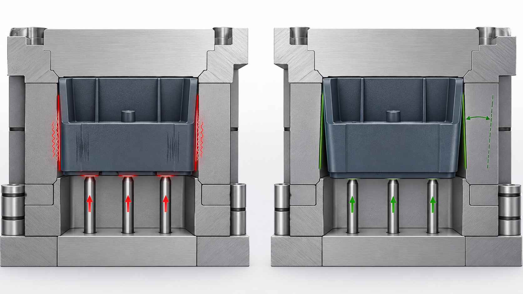
- Reliable part ejection. As the polymer cools, it changes dimensions. A part may grip a core more tightly or remain held in the cavity. Draft lowers the force needed to release it.
- Surface protection. With insufficient draft, the part wall slides along the mold steel under higher friction. That can cause scuffing, scratches, and drag marks.
- Lower load on the ejection system. The more easily the part separates from molding features, the lower the risk of ejector-related deformation and local witness marks.
- Stable cycle operation. Predictable release reduces the likelihood of sticking, manual intervention, and injection-molding-machine stoppages.
- Reduced wear on molding surfaces. Repeated part-on-steel friction accelerates wear, especially with textured surfaces and abrasive filled materials.
What happens when draft is insufficient
Insufficient draft does not always create scrap on the first cycle, but it creates a process risk that may appear during process development, material changes, or as the mold accumulates cycles.
Typical signs include:
- the part remains on the wrong mold half or sticks to a core;
- drag marks, scratches, or localized surface haze appear;
- ejector pins leave marks, distort thin areas, or do not provide reliable release;
- ejection-force variation and the number of production stops increase;
- polished or textured molding surfaces wear faster;
- manual intervention is needed, increasing the risk of damage to both the part and the tool.
Correcting draft after the mold has been built is much more difficult than adding it to the model. It can require reworking molding features or producing new inserts, which is why draft should be reviewed before tooling is released for manufacture.
How much draft to use
Draft should be selected for the actual geometry rather than applied as a single universal rule. Common starting points for smooth surfaces are:
- 0.5° — a possible lower limit for shallow, smooth features under favorable ejection conditions;
- 1°–2° — a practical range for many smooth walls;
- 3° or more — often needed for deep features, textured surfaces, higher-friction zones, or demanding ejection conditions.
These are not a finished specification for every part. The final draft depends on the polymer, feature depth, mold surface finish, whether the part is formed on the core or cavity side, ejection forces, and cosmetic requirements.
When agreeing on draft, it is useful to define the functional edge or surface from which it starts. This helps preserve critical fit dimensions and assembly interfaces.
Factors that influence the required draft
Feature depth. The taller the wall, deeper the rib, or longer the contact area with the mold, the more frictional area is involved and the more important adequate draft becomes.
Surface finish and texture. A polished surface usually releases more easily than a textured one. Texture creates micro-relief that can mechanically engage with the part during ejection.
Material. Shrinkage, stiffness, modulus, coefficient of friction, and filler content influence how the part holds onto a core or remains in a cavity. Recommendations for a specific grade should be confirmed during DFM and mold trials.
Part side. Internal surfaces formed on a core often need special attention because shrinkage can increase the gripping force on the core. Draft and surface finish also matter on external surfaces, although the retention mechanism can be different.
Ejection direction and parting-line placement. In some cases, selecting a better pull direction is enough to provide draft without changing functional geometry. In others, additional molding features or moving units are needed.
Texture and draft: a critical relationship
Textured surfaces require their own assessment. The deeper and coarser the texture, the more draft is needed to release the part without drag marks.
A commonly used starting guideline is to add approximately 1°–1.5° of draft for every 0.025 mm (0.001 in.) of texture depth beyond the base value for a smooth surface. It should not be applied mechanically: the final recommendation depends on the texture type and direction, polymer, feature depth, and the texture supplier’s requirements.
Light texture is often evaluated with roughly 3° of draft, while more pronounced texture may require 5° or more. The final angle should be agreed with the texture supplier and mold designer before the part model is approved.
Where draft is needed on a part
Draft should be checked not only on external housing walls. It is often needed on:
- internal walls of box-shaped parts and deep pockets;
- stiffening ribs, especially tall and thin ribs;
- bosses for screws, inserts, or mounting features;
- holes, projections, and guides formed along the ejection direction;
- moving mold elements such as slides, strippers, and inserts if the surface contacts a molding feature during opening.
Draft must not compromise the part’s function. Fits, sealing faces, guides, and mating features should be designed with a clear decision on where taper is acceptable and where a controlled size or a different tooling solution is required.
Can draft be zero?
Functional or cosmetic requirements can sometimes limit draft to a minimum or require a locally zero-draft surface. This is possible, but it needs a separate engineering decision.
Such areas may require:
- high-quality polishing of the molding surface in the ejection direction;
- more precise ejection design and force distribution;
- a different pull direction or parting-line layout;
- separate inserts, strippers, moving cores, or slides when the geometry cannot be released directly;
- confirmation during mold trials.
Zero draft is not automatically a mistake, but without analysis it raises the risk of marks, sticking, and faster tool wear. It should be used only in critical areas with a clear understanding of the process constraints.
Why draft should be checked in the 3D model
Adding or changing draft in a CAD model is normally much faster and less expensive than correcting a finished steel mold. During DFM, engineers can assess:
- mold opening direction and undercuts;
- draft adequacy on every surface along the ejection direction;
- the effect of draft on critical dimensions and assembly interfaces;
- compatibility of texture, material, and release method;
- the need for slides, strippers, or separate inserts.
This review helps align part design, manufacturability, tooling cost, and serial-production stability before machining begins.
How Promservice helps with draft and manufacturability
Promservice treats draft as part of the overall preparation of a part for injection molding. During project preparation, we can:
- analyze the 3D model and ejection direction;
- check draft, undercuts, and the risk of difficult release;
- recommend starting values based on material, feature depth, and texture;
- align changes with the part’s functional requirements;
- design the mold, ejection system, and moving units;
- manufacture the tooling, perform trials, and set up serial production of plastic parts on our own injection molding machines.
Need a DFM review for an injection-molded part?
Send us a 3D model or drawing, information about the material, surface requirements, and expected production volume. Promservice specialists will review the draft angles, ejection direction, and other manufacturability parameters, helping prepare the part for mold manufacturing and serial production.